| OCR Text |
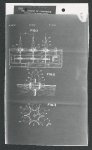
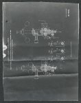
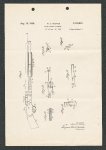
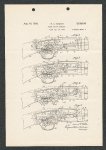
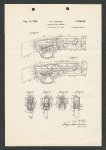
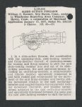
Show 2 2,126,816 usual gun-barrel 26, below which is mounted a tubular magazine 27 which latter is adapted in the usual manner of tubular magazines to successively feed cartridges into the lower forward end of the chamber 22 in the receiver 20. The magazine 27 serves as a guide and support for a reciprocating slide-handle 28 preferably formed from wood or other heat-insulating material and mounted upon an operating-sleeve 29 which encircles the said magazine 27 and has projecting from it an operating slide-bar 30 which extends rearwardly into the chamber 22 in the receiver 20 for reciprocation in and guidance by a guide-groove 3! formed in the integral left side wall 32 of the said receiver 20 opposite the open face 21! thereof. The rear end of the operating slide-bar 30 is operatively connected to a reciprocating and tilting bolt 33 with freedom for limited relative movement with respect thereto, as will hereinafter appear, by means of a stud 34 mounted adjacent the extreme rear end of the said bar 30 and inwardly projecting therefrom into a substantially L-shaped cam-groove 35 formed in the left side of the said bolt 33 and consisting of a depressing-and-retracting cam-surface 36, a closing-and-lifting cam-surface 317, and a boltlocking surface 38, with which latter the said stud 34 is normally engaged when the said operating slide-bar 30 is at or near the limit of its forward movement, as shown in Figs. 4 to 7 inclusive. When the operating slide-bar 30 and the bolt 33 are at the limit of their forward movement and the bolt-locking surface 38 is resting upon the stud 34, the bolt will be locked against downward tilting movement by the said stud and will be locked against rearward displacement by having its locking-lug 39 entered into a lockingrecess 40 formed in the under surface of the upper wall 41 of the receiver 20, with the sloping rear surface of the said lug engaged with the similarly sloped rear wall of the said lockingrecess 40. In the bolt 33 is mounted a reciprocating firing-pin 42 which may be of any approved construction and normally has its rear end 43 projecting beyond the rear end of the bolt for hbeing struck by a suitable hammer, as will hereinafter appear. The forward end of the bolt is formed with a forwardly-projecting cylindrically-contoured extension 44 which is adapted to seat within a similarly-shaped recess 45 formed in the receiver 20 immediately adjacent the rear end of a concentric cartridge-chamber 46 formed in the rear portion of the barrel 26, the rear face of which latter provides a seat 417 for the rim of a cartridge. The bolt 33 is also provided with the usual complementary extractors 48 adapted to engage the rim of a cartridge and extract the same from the chamber 46 when the bolt is moved rearwardly. The under face of the bolt 33 is formed centrally with a longitudinal upwardly-and-rear5 wardly-sloping hammer-receiving groove 49 having the extreme rear end of its top wall 50 chamfered as at 5! and adapted to engage and override a pivotal hammer 52. The said hammer 52 is pivotally mounted upon a transverse pin 53 mounted in the bottom wall 54 of the receiver 20 just to the rear of the loading-opening 85 therein. The said hammer is provided upon its rounded lower end with a sear-abutment 56 adapted to be engaged by a sear-finger 57 forwardly projecting from a sear-arm 58 constituting the up- per forward arm of a trigger 59 pivotally mounted upon a transverse pin 69 in the lower wali 54 of the receiver and having its finger-piece 61 operating within a trigger-guard 62 formed integral with the said receiver, as shown. Pivotally connected to the hammer 52 by means of a transverse pin 63 is the forward end of a plunger 64 serving also, in the construction shown, as a hammer-spring guide-rod and having sliding bearing in a diametrical passage 65 formed in an oscillating guide-member 66 which also serves as a spring-abutment. The said guide-member is formed at each of its respective opposite ends with a cylindrical trunnion 67, each of which oscillates in a forwardly-andupwardly-sloping notch 68 formed in the receiver 20. The respective trunnions 67 of the guide-member 66 are maintained in their respective notches 68 by a hammer-spring 69 encircling the plunger 64 and abutting at its rear end against the said guide-member 66, while its forward end abuts against the rear face 70 of the head portion Tf of the said plunger. The guide-member 66 has rigidly mounted in one of its cylindrical trunnions 67 the rear end of a wire-like slide-lock operating-spring 72, the forward end of which extends into a bearingpassage 73 formed in the laterally-extending portion 74 of an oscillating sheet-metal slidelocking member 175. The said slide-locking member 75 is mounted for rocking movement in a vertical plane upon a transverse stud 16 mounted in the receiver 20, before referred to. The extreme rear end of the slide-locking member 75 is transversely bent to provide a releasing-member 77 and is formed about midway of its length with an upwardly-and-forwardlysloping guard-finger 18, for the purpose as will hereinafter appear. At its forward end, the said member 15 is provided with an upwardly-extending wedge-shaped slide-locking nose 78. The sloping forward end 80 of the slide-locking member 15 is adapted to act as a locking-abutment, as will hereinafter appear, and is formed with a forwardly-offsetting semicircular retaining-lip 81 adapted to slide within an under-cut groove 82 formed in the left side-wall 32 of the receiver 20. The guard-finger 78 of the slide-locking member 75 is adapted under certain conditions to be moved over the upper forward corner 83 of a suard-ledge 84 formed upon the left side of the hammer 52, when the said hammer is in its rearwardly-swung position, aS shown in Figs. 2, 3, 4 and 7. The said guard-finger 18 is engaged by the corner 83 of the ledge 84, just referred to, to guard against the movement of the said hammer prior to the movement of the bolt 33 into its fully-closed and locked position, as will more fully appear from the following. For the purpose of enabling the user of the firearm to unlock the bolt 33 and move the same into its fully-retired position shown in Fig. 2 without first requiring the release of the hammer 52, I provide manually-operable means for rocking the slide-locking member 15 to withdraw its locking-nose 79 from the path of the operating slide-bar 30 and out of engagement with the rear end 85 thereof. The said rear end 85 of the slide-bar 30 is sloped, as shown, to correspond to the slope of the forward end 80 of the slide-locking member 175, for the purpose of securing a frictional engagement between the two said surfaces, for the purpose as will hereinafter appear. The means above referred to, for manually un- |