| OCR Text |
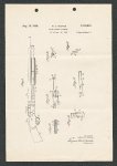
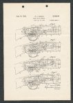
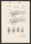
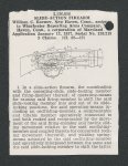
Show 2,126,816 locking the bolt 33, consists, mainly as shown in Figs. 7, 11 and 17, of a vertically-reciprocating releasing-member 86 which includes a fingerbutton 87 and a cylindrical upwardly-extending shank 88, which latter is adapted to engage with the under-surface of the releasing-finger TT, before described, which extends laterally from the rear end of the slide-locking member 15. As shown particularly well in Fig. 15, the operating slide-bar 30 is formed in its right under corner with a longitudinal groove 89 terminating at its rear end in a downwardly-curved camsurface $3 adapted to cam the slide-locking nose 79 of the slide-locking member 75 downward as the said slide-bar is moved forward from its rearmost position for the purpose as will hereinafter appear. For the purpose of normally maintaining the rear end 85 of the operating slide-bar 30 in frictional engagement with the similarly-sloped forward end 88 of the slide-locking member 75 when the breech is in its fully closed position, I employ a sheet-metal spring 9! which encircles the tubular magazine 27 and has its respective ends laterally offset in opposite directions, as shown in Fig. 1. One of the laterally-offset ends of the said spring 9! engages the forward end of a collar §2 soldered, brazed, or otherwise secured to and within the sleeve 29 of the slide-handle 28 and adapted to slide freely upon the said magazine 2T. The complementary oppositely-offset end of the spring 9! is adapted to abut against the rear edge of a collar 93 encircling the magazine 27 and to which it is secured by solder, brazing, or otherwise, and upon the outer periphery of which the sleeve 29 of the slide-handle 28 is adapted to freely slide. For the purpose of making clear the operation and functioning of the slide-action firearm herein chosen for illustration, let it be presumed that the slide-handle 28 has been manually moved to the limit of its rearward movement, with the effect of moving the parts into the positions in which they are shown in Fig. 2, in which figure it will be noted that the bolt is fully retired, so that a cartridge may be introduced into the chamber 46 either directly or from the magazine 21 by means of suitable mechanism (not shown). If, now, the slide-handle 28 is moved forwardly so as to move the bolt from the position in which it is shown in Fig. 2 into the position in which it is shown in Fig. 3, the cam-surface 99 on the operating slide-bar 39 will have engaged the nose 18 of the slide-locking member 75 with the effect of depressing the same and thereby rocking the entire slide-locking member about its pin 76 in a clockwise direction, with the effect of causing the guard-nose 78 of the said member 175 to move into camming engagement with the corner 83 of the O guard-ledge 84 of the hammer 52 to thus further depress the said hammer and cause its searabutment 56 to move slightly out of contact with the sear-nose 57 of the trigger 59, though the said sear-nose remains in the path of the said » abutment, as will clearly appear by reference to Fig. 3. The clockwise rocking movement of the slidelocking member 75 caused by the action of the cam-surface 90 of the operating-slide 30, as just above described, will occur against the tension of the operating-spring 72, which latter, under the conditions above described, will exert a constant effort to swing the locking-member 15 in a counterclockwise direction. The continued forward movement of the slide- 3 handle 28 to the limit of its forward movement, in which the spring 9! is placed under tension, will move the bolt bodily forwardly and rock the same upwardly into its locked position, as shown in Fig. 4. During the forward travel of the operating slide-bar incident to the moving of the bolt into its fully closed position, as just described, the rear end 85 of the said slide-bar 30 will be moved forwardly of the forward end 89 of the slide-locking member 75 and thus permit the already tensioned spring 72 to rock the member 175 in a counterclockwise direction and move the nose 7§ thereof upwardly into the path of the said slide-bar 30. Upon the release of the forward manual thrust upon the slide-handle 28 the spring 91 will assert itself and cause the rear end 85 of the slide-bar 29 to frictionally engage with the forward end $0 of the slide-locking member 175 to frictionally hold the same in the position in which it is shown in Fig. 4 for the purpose as will hereinafter appear. As the slide-locking member 175 is rocked in a counterclockwise direction, as just described, its guard-nose 78 will thereby be moved out of engagement with and out of the path of the corner 83 of the guard-ledge 84 and thus permit the hammer 52 to swing to a slight degree in a clockwise direction to reengage its sear-abutment 56 with the sear-nose 57. As the operating slide-bar 30 is moved forwardly from the position in which it is shown in Fig. 3 into the position in which it is shown in Fig. 4, its stud 34 will have engaged the closingand-lifting cam-surface 37 of the bolt 33 so as to first move the said bolt to the limit of its forward movement and subsequently tilt the rear end of the same upwardly to engage the rear surface of its locking-lug 39 with the rear wall of the locking-recess 49. After the bolt has been moved forwardly and tilted, as just described, the stud 34 will under-ride the locking-surface 38 thereof and support the bolt in its locked position. With the parts in the positions shown in Fig. 4, the gun is in condition for firing, which may be effected in the usual manner by a rearward draft upon the finger-piece 61! of the trigger 59. The rearward draft upon the finger-piece 61! of the trigger will disengage the sear-nose 57 from the sear-abutment 56 and thus permit the hammer-spring 69 to drive the hammer 52 in a clockwise direction and cause the upper portion of its forward face to impinge against the rear end 43 of the firing-pin 42, as shown in Fig. 5, which illustrates the position of the parts at the instant the said hammer engages with the said firing-pin and just prior to the forward travel of the latter to fire the cartridge. As the hammer 52 swings in a clockwise direction, as just above described, the plunger 64 will have moved bodily forwardly in the passage 65 of the guide-member 66, and will at the same time have been rocked in a counterclockwise direction, and similarly rock the said guide-member 66, as may be observed by comparing Fig. 4 with Fig. 5. The counterclockwise turning movement of the guide-member 66 will serve to reversely tension the operating-spring 12, which will now tend to swing the slide-locking member 15 in a clockwise direction and, therefore, tend to move the locking-nose 179 thereof out of the path of the operating slide-bar 39. However, owing to the rearward pressure exerted upon the said slide-bar 30 by the spring 91, the frictional engagement between the rear end 85 of the said slide-bar and the forward end 80 of the member 4! ! 5: 7 |