| OCR Text |
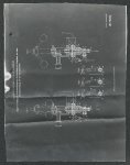
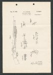
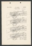
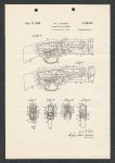
Show 4 2,126,816 15. will be sufficient to prevent the operatingspring 12 from effecting the clockwise turning movement of the member 75 until such time as recoil takes place in the firearm, as will be presently described. As the hammer 52 drives the firing-pin 42 forwardly from the position shown in Fig. 5 to that shown in Fig. 6 (which movement requires but a fractional part of a second), the gun will be fired, with the effect of causing the same to recoil and, owing to the fact that the slide-handle 28 is slidably mounted upon the magazine 21, the said slide-handle and its rigidly connected parts including the operating slide-bar 30 will, ; due to their inertia, and despite the tension of the spring 9!, not immediately partake of the rearward movement of the remainder of the fire arm under the action of the recoil just referred to, but will lag behind, with the effect that the slide-locking member 175 (which immediately partakes of the recoil movement) will move rearwardly relative to the said slide-bar 39 and disengage the forward end 80 of the former from the rear end 85 of the latter, whereupon the slide-locking member will immediately turn in a clockwise direction under the urge of the operating-spring 172, so that the slide-locking nose 19 will be fully retired out of the path of the operating slide-bar 30. The parts will now have assumed the positions in which they are shown in Fig. 6. The operating slide-bar 30 having been unlocked, as above described, may now be manually moved rearwardly by means of the slide-handle 28. This latter action will effect the retirement of the bolt 33 for the purpose of extracting the now fired cartridge from the chamber 46 and to permit the introduction of a fresh cartridge thereinto. As the slide-bar is moved rearwardly for the purpose just above described, the stud 34 thereof will move rearwardly out from under the boltlocking surface 38 of the L-shaped cam-groove 35 of the bolt and into engagement with the depressing-and-retracting cam-surface 36 thereof, with the effect of first rocking the rear end of the said bolt downwardly to disengage its lockinglug 39 from the locking-recess 40 and then moving the said bolt bodily rearward and ultimately into the position in which it is shown in Fig. 2. As the bolt 33 is moved rearwardly, as above described, the rear end 43 of the firing-pin 42 will first be engaged with the hammer 52, with the effect of starting the swinging movement of the same in a counterclockwise direction against the tension of the spring 69. As the hammer rocks rearwardly, as described, it will subsequently be engaged by the chamfered surface 5! and ultimately by the top wall 50 of the hammer-receiving groove 49 in the said bolt, with the effect of tilting the said hammer sufficiently to cause its sear-abutment 56 to move over the sear-nose 517 and slightly past the forward end thereof. As the hammer 52 is swung in a counterclockwise direction as just above described, the spring 69 will be further compressed and the plunger 64 will be moved rearwardly, through the passage 65 in the guide-member 66, with the effect of turning the said guide-member in a clockwise direction sufficiently to reverse the tension of the operating-spring 72 and cause the same to yieldingly urge the slide-locking member 15 in a counterclockwise direction. At substantially the same time that the rear end of the guard-ledge 84 of the hammer 52 reaches the forward end of the guard-finger 78, the rear end of the groove 89 in the slide-bar 30 will have been brought into line with the locking-nose 79 of the member 175, whereupon the said nose will rise under the tension of the spring 72 and the said member 15 will turn in a counterclockwise direction to a degree sufficient to retire the guard-finger 78 out of the path of the said ledge 84 and thus permit the hammer to pass rearwardly and downwardly into, its fully retired position. The parts will now have reassumed the positions in which they are shown in Fig. 2, preparatory to another cycle of operations corresponding to that already described. In the event that after the gun is cocked and the breech closed, it should for any reason be desired to move the bolt into its fully retired position such, for instance, as to extract an unfired shell from the cartridge chamber, this may be accomplished without releasing the hammer, by an upward pressure exerted upon the finger-piece 87 of the releasing member 86 to cause its shank 88 to engage the under face of the releasingfinger 17 of the slide-locking member 175 and thus rock the latter member in a clockwise direction to forcibly depress its locking-nose 719 and move the same out of the path of the operating slide-bar 30, as shown in Figs. 7 and 11. With the locking-nose of the member 15 retired as just above described, the slide-handle 28 may be moved rearwardly and through the intermediary of the operating slide-bar 30 effect the unlocking and retirement of the bolt 33 into the position in which it is shown in Fig. 2. Particular attention is called to the fact that by utilizing the swinging movement of the guidemember 66 or its equivalent, to reversely tension an operating-spring, not only is substantially the entire swing of the hammer utilized to effect the action referred to but a direct action is achieved which is both reliable and effective and lowers the cost and avoids the complexity of additional parts. The invention may be carried out in other specific ways than those herein set forth without departing from the spirit and essential characteristics of the invention, and the present embodiments are, therefore, to be considered in all respects as illustrative and not restrictive, and all changes coming within the meaning and equivalency range of the appended claims are intended to be embraced therein. I claim: 1. In a slide-action firearm, the combination with the operating-slide, slide-locking member and firing-member thereof; of operating-means for causing said firing-member to shift the said slide-locking member into and out of its slidelocking positions, the said operating-means including an oscillating-member, a reciprocatable and tiltable member operatively connected to and both rocked and reciprocated by the movement of the said firing-member and having sliding movement relative to the said oscillatingmember and coupled thereto for concurrent rocking movement therewith, and yielding springmeans actuated by the said oscillating-member and operatively interposed between the same and the said slide-locking member to shift the latter. 2. In a Slide-action firearm, the combination with the operating-slide, slide-locking member and pivotal hammer thereof; of operating-means for causing said pivotal hammer to shift the said slide-locking member into and out of its slide-locking positions, the said operating-means |